Categories
Browse by:

TOA PA System Amplifier Guide
| When designing and installing sound systems, mastery of some key concepts helps a great deal. A basic understanding of signal flow, levels, and impedance can increase your efficiency on the job, and dramatically reduce the number of costly call-backs. | |
| Code: | TOA |
TOA Amplifier Signal Flow, Level and Impedance
When designing and installing sound systems, mastery of some key concepts helps a great deal. A basic understanding of signal flow, levels, and impedance can increase your efficiency on the job, and dramatically reduce the number of costly call-backs.
Signal Flow: The Audio Chain
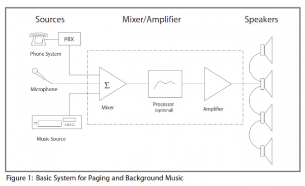
Signal Flow refers to the path of the sound from the source (paging announcements, Bluetooth, CD player, satellite receiver, etc.) to the listener. This path can be very simple, using just a single source, a power amplifier, and one or more speakers, or it can be complex, having multiple sources, multiple paths, and multiple destinations, with extra processing stages. A typical paging system signal path will begin with two or three sources for example, background music, paging audio from the phone system, and a microphone (see fig. 1). These will be fed into a mixer, which combines the sources into one single line. The mixer output may be fed into an equalizer, compressor or other processor, or directly to an mixer amplifier. The amplifier increases the power of the signal and feeds it to the speakers. In most smaller systems, the mixer and amplifier sections are integrated in one unit, which may include a built-in or optional processing stage, such as an equalizing module for premium speakers.
More complex systems include all these same stages sources, mixing, processing, amplification, and speakers but may add additional signal paths (called busses) so that some sources or listening areas can be treated differently. A common addition to the typical paging system is the Music On Hold (MOH) output bus. This bus is fed from the music input, and not affected by speaker processing modules or by mute functions used for the overhead paging (see fig. 2). TOA 900 Series amplifiers can provide an MOH output using the T-12S module, which provides for both the music input and the MOH output. This module also works with the 900 Series mute bus to allow for muting of the music during paging announcements to the main output, while the separate MOH output is not muted and receives no page announcement. TOA BG and BG-M Series amplifiers include MOH outputs as standard features.

Zone paging and multimedia systems can use additional signal paths to route sounds to different areas (see figs. 3 and 4). Figure 3 shows a typical 3-zone paging system for central mic and/or telephone paging with background music. Simple contact closures, provided by the phone system or contractor, are used to activate the zones in any desired combination, simultaneously muting the background music in each activated zone. TOA BG-M Series amplifiers offer an especially economical solution for this type of zone paging system. The background music may be from sources local to each zone or distributed from the head-end via the MOH output.
In multimedia applications, multiple signal paths can be used to route speech and music or movie sound to different speakers, allowing precise matching of speaker type for the intended application. Figure 4 shows a multimedia system for a lecture hall, training room, or multi-media-ready meeting room. This system provides for stereo playback of music sources and stereo sound for video, using a pair of speakers which may be located flanking a fixed or retractable screen, alongside distributed mono speech. The resulting system can provide powerful and moving reproduction of music and movie soundtracks and clear, intelligible speech. An optional subwoofer for the music feed further enhances the impact.

Audio Levels: Voltage, Gain and the Decibel
A basic characteristic of any audio signal is its amplitude, measured electrically in terms of voltage or acoustically in terms of sound pressure. When assessing the loudness of a signal, the amplitude or pressure is converted to a decibel value. The decibel scale gives a relative number referenced to a certain voltage or pressure. For example, 0 dBV is a popular standard reference for audio levels, and represents one volt. Note that amplitude is expressed as a voltage, while level (or loudness) is expressed using a dB scale.
When working with audio electronics, levels are commonly divided into three ranges: mic level, line level, and speaker level. Mic level is the smallest signal. Microphones and other passive transducers (devices that convert energy from one form, such as sound, to another, such as electricity) produce signals ranging from a few microvolts to a few millivolts. A typical nominal operating level for a microphone output would be 55 dBV. Line level is hundreds of times greater in voltage terms typically ranging from several millivolts up to around 1 volt, with a nominal level of 0 dBV. Speaker level is the strongest, ranging from a fraction of a volt (during quiet periods) to several dozen volts depending on the output rating of the amplifier. Of course, sound is very dynamic in nature, so whatever the nominal operating level of your signal is, if you read it with a meter during operation, you are likely to see large fluctuations from moment to moment within that range.
An important function of amplifiers is providing the 'gain' needed to raise signals from mic or line level up to speaker level. Gain is another word for amplification, and simply means an increase of the voltage or power. The opposite of gain is attenuation. Both gain and attenuation are commonly measured in decibels.
The dBV scale is not the only one used for audio levels. Another popular reference scale is the dBu, where 0 dBu represents 0.775 volts. The historical predecessor to these two scales is the original dBm scale, where 0 dBm represents one milliwatt, or 0.001 watts. Other scales you might encounter include dBW (referenced to one watt) and dBµV (referenced to one microvolt). These scales are seen mostly in the radio broadcast industry. Care should be taken not to confuse one scale with another, especially the common dBV and dBu scales. To make things especially aggravating, the term for dBu was previously dBv with a lower-case 'v'; so if you encounter dBv on an old spec sheet, it means dBu, not dBV.
Figure 5 shows a simplified block diagram and a level diagram, indicating gain stages inside a mixer amplifier, from mic and line level inputs to 70.7 volt speaker level output. The signal is amplified in stages, with attenuators (volume controls) between each stage to reduce the overall gain when needed. The mic pre-amp provides 32 to 52 dB of gain, bringing the mic level signal up to a level that can be matched with other line level sources. The summing amplifier provides additional gain, bringing all sources up to 0 dBV. The power amplifier serves to boost the power up to a level that can drive a speaker. It also provides a low output impedance for efficient power transfer. Lastly, the output transformer matches the amplifier to the 70.7 volt line and increases drive voltage to a maximum rated output of +37 dBV.
Impedance
Impedance refers to the way a device reacts to the application of electric current. The device will exhibit varying amounts of resistance and either capacitance or inductance. For our purposes, the resistance is most important. In keeping with common practice, when we say 'impedance' we will mean resistance.
Impedance, in this sense, refers to how much resistance the device presents to the free flow of electricity through it. At a given drive voltage, the lower the impedance of the receiving device, the higher will be the current flow through it. This is important to know when working with amplifiers, because if the load impedance presented by the speakers is too low, it may draw so much current that the amplifier will overwork itself and deliver distorted sound, overheat perhaps even burn out. Impedance is measured in ohms, named for Georg Ohm, who first described the set of electrical relationships now known as Ohm's Law (see fig. 6). Every device will have both an input impedance (also called the load impedance) and an output impedance (also called the source impedance). The input impedance of an amplifier could range from 600 ohms to 10,000 ohms, or even higher (see side bar). A typical speaker impedance may range from 4 to 16 ohms.
Impedance 'Matching' A common point of confusion is the concept of 'impedance matching.' Transmission line theory states that the load impedance and source impedance should be equal, to avoid reflections in the line. But this requirement holds only when the line is longer than the shortest wavelength of the signal. For audio frequencies, the line would need to be over 9 miles long for transmission line theory to apply. When using solid-state equipment and typical cable runs of several hundred feet or less, the best performance is obtained when the load impedance is about 5 to 20 times greater than the source impedance. So, for example, a 10,000 ohm input is a good 'match' for a 600 ohm output.
Amplifier Speaker Matching
Interfacing between the amplifier and speakers is commonly done in one of two ways. Small systems with one or two speakers will typically use a direct connection between the speakers and the amp. This is sometimes called low impedance operation, because the load impedance ranges from 4 to 16 ohms nominal. Systems with more than 2 speakers usually use transformers at the amp and at each speaker to simplify impedance matching and reduce line loss. These systems are commonly called distributed line systems, 70.7 volt (or 25 volt) systems, or constant voltage systems. In both cases, speakers should be wired in parallel (plus to plus and minus to minus).
Low Impedance Systems
When matching amplifiers with speakers, there are a couple of important rules to remember. First, low impedance amplifier outputs are described in terms of the recommended load impedance, i.e. 4 ohm output' or 8 ohm output' (the actual source impedance of a power amplifier output is seldom specified but is typically less than one ohm). Second: With rare exceptions, when using more than one speaker, the speakers should be wired in parallel.
Parallel wiring always results in a lower load impedance than the individual rating of each speaker. For example, two 8 ohm speakers in parallel results in a 4 ohm load. Two 16 ohm speakers in parallel results in an 8 ohm load. The general-purpose equation for calculating the load of multiple speakers in parallel is shown in Figure 7. But as the above two examples illustrate, you will find that when all the speakers have the same impedance, the total load will be equal to the rated impedance divided by the number of speakers.
A commercial-grade speaker without any transformer may have a rated nominal impedance anywhere from 4 ohms to 16 ohms. The most common ratings are 4 ohms, 8 ohms or 16 ohms. The most common recommended load ratings for low impedance amplifier outputs are 4 ohms and 8 ohms. This means that in most cases, you will be limited to one or two speakers per amp channel when connecting low impedance speakers in parallel.
High Impedance (70.7 Volt / 25 Volt) Distributed Line Systems
In order to overcome the limitations of low impedance speaker systems, most medium-scale installed sound systems in the United States use either 70.7 volt or 25 volt distributed line systems, also known as high impedance or constant voltage systems. Often, they will be called simply '70 volt' or '25 volt' systems.
These systems work by including transformers at the input to each speaker and directly after the amplifier output (see fig. 8). The transformers are used to convert the impedance of each speaker to a higher value, and to convert the amplifier output impedance to a correspondingly high value. In a 70 volt line system, speaker impedances (with transformers) may range from below 20 ohms to as high as 10,000 ohms or more. But you won't need to calculate the load impedance in ohms, because of how the high impedance approach works.
High impedance (70.7 volt and 25 volt line) systems have three major advantages over low-impedance
systems:
- System impedance-matching is made much easier it is simply a matter of adding up speaker power taps and selecting an amplifier rated for at least that much power plus an allowance for headroom.
- Line loss is greatly reduced, especially over long cable runs, resulting in better performance and reduced cost compared to long low impedance lines.
- The amplifier output is electrically isolated from the speaker line by the output transformer, protecting the output stage against a grounded line and thus eliminating a potential source of system failure.
How To Design A High Impedance Distributed System
In designing a high impedance speaker system, there is no need to calculate the total impedance from the speaker impedance values, the way you would for a low impedance system. This is because in high impedance systems (i.e. 70.7 volt and 25 volt line systems), the load impedance rating is expressed in terms of the amount of power that would be delivered to it at the rated line voltage. The rating is given in Watts, which can simply be added to the other speakers to get the total power drawn by the load. Just add a little extra for headroom (see example below), and you know how much power is needed. You don't even have to know Ohm's Law.
Here's the process in more detail: You should begin by choosing the type of speakers, how many, and how much power each one will need in order to reach the desired volume in the listening area. Help with this can be found in the TOA Speaker Guide. Once you know the type(s) of speaker(s) and how much power each one will need, determine what is the lowest available transformer tap that will supply at least that much power to the speaker. For example, the SC-615T has 70.7 volt transformer taps at 15, 7.5 and 3.8 watts. To reach your desired level (maximum average level plus headroom for short-term peaks), you decide you'll need at least 5 watts at the speaker. In this case, choose the 7.5 watt power tap.
When you have selected the proper power tap for each speaker, simply add them up and multiply the total times 1.25. Your amplifier should have at least this much power into the selected line voltage. For example, the job requires twelve SC-615T horns, each tapped at 7.5 watts, to cover the listening area. Twelve times 7.5 watts = 90 watts, and 90 watts times 1.25 = 112.5 watts. Your amplifier should have at least this much power.
The 'audio chain' analogy is an especially good one when talking about wiring.
Like a chain, a sound system is only as good as its weakest link. The kinds of cables used and how they are connected can often be the difference between a great system and a useless one. Most experienced audio professionals can tell stories about contractors who have saved a few pennies on installation and wiring costs, only to spend costly hours back on site correcting noise or other problems later. The kind of wire to use will vary depending on the kind of signal it will be carrying, as well as the environment it will be used in. For most commercial installations, wiring will be 'jacketed,' meaning that the insulated conductors will be bundled together, often in twisted pairs, inside an overall jacket for extra protection.
Low level and Line Level Wiring: Twisting, Shielding, Balancing and Isolating One of the challenges in sound engineering is to avoid the introduction of unwanted electrical noise and interference into the system. Unwanted noises enter the system in one (or both) of two ways: Induced noises can come into the system from sources that are not directly connected, much as radio waves can be picked up at a distance. In fact, radio waves are one of the main sources of induced noise (this type of noise is called radio frequency interference, or RFI). Induced noises may also be the result of inductance or capacitance between cable conductors and other conductors nearby (often called electro-magnetic interference or EMI, and electro-static interference). Common sources of induced noise include electric motors, radio transmitters, some types of lighting equipment, digital circuits, all kinds of power supplies. Indeed, in microphone applications, if you use the wrong cable, then just about any circuit where AC current is flowing could be a source of induced noise.
The good news is most induced noises are easy to control by choosing the right type of cable and input/output circuit. Ground loops come from ground reference mismatches, which are a function of the power source(s) used for the sound system. If a mixer/amplifier is plugged into one AC outlet, and the input signal comes from a source that is plugged into a different outlet elsewhere in the building, the ground wires at the two outlets might have slightly different voltage potentials with respect to ground (and more importantly, with respect to each other). If the signal ground is tied to the AC mains ground, as is commonly the case in unbalanced audio circuits, then connecting the audio cables from the source to the mixer/amplifier will complete a circuit through which will flow a voltage equal to the potential difference between the two AC mains grounding points. This circuit is called a ground loop. The main symptom of a ground loop will be a 60 Hz hum in the sound system, often with harmonics above this at multiples of 60 Hz.
There are three ways to alleviate ground loops, or avoid them altogether:
- Use the same AC outlet for all equipment in the system. This may be impractical, if distances are great, or even inappropriate if the current draw exceeds the rating of the AC circuit.
- Use transformer isolation between sound system components (see page 16).
- Use a 'floating' balanced line for the audio signal, so that neither leg of the signal is tied to ground (see page 16). Often, methods 2 and 3 are combined with the use of transformer-balanced inputs and outputs.
The two most popular methods to reduce the pickup of induced noises through sound system wiring are the use of twisted pair wiring, and the use of shielded cable.
Twisted Pair Wiring
Twisted pair wiring is just what it sounds like: two insulated conductors are twisted around each other over the length of the cable run. The twisting has the effect of rejecting certain types of induced noise, since each half-turn of the wire exposes it to the noise source with the opposite polarity of the preceding half-turn. The effect also works in reverse: twisted pairs generate less noise than pairs run in 'flat,' untwisted wire. This fact helps to reduce the effect of 'crosstalk' between pairs when multiple lines carrying similar signals are bundled together.
Twisted pairs have been used by telephone companies for the better part of a century to carry voice communications, and are now the standard type of cable for Ethernet networking and other data transmission protocols (for example, CAT 5 wiring is simply a set of twisted pairs). In sound systems, twisted pairs are often used for speaker wiring, especially over longer distance runs. For other sound system applications, twisted pair wiring is seldom used, except in conjunction with shielding and balancing (see Balanced and Unbalanced Lines, below). So, while CAT 5 may be the cat's meow in data networking, you don't want to use it for your microphone wiring, or you risk serious noise problems.
Shielded and Unshielded Cable
Shielded cables are the most common, and a more effective, line of defence against noise pickup in audio applications. They protect the signal path from noise pickup by surrounding one or more of the cable's conductors with another conductor (the shield) that is tied to ground at one or both ends of the line. Shielded cables should always be used for microphone wiring. They should also be used for all unbalanced line level wiring, such as the outputs of CD players, tape decks, or many other common music sources. Standard stereo RCA patch cords are a common example of shielded wiring for unbalanced sources.
Balanced and Unbalanced Lines
The most effective defence against the pickup of induced noise through the wiring is to use a 'balanced' circuit for the connection between equipment. This method involves not only using the right cable, but also having a certain type of input and output circuit. In sound systems, balanced circuits, or balanced lines, are typically run using three conductors a twisted pair of inner conductors surrounded by a shield conductor.
Running a balanced line requires the use of balancing output and input circuits, which work by splitting the signal into two paths, then inverting the polarity of one path, so that each conductor carries a signal that is the exact electrical opposite of the signal on the other conductor. While the signal is carried by the two conductors in opposite polarity, the noises that accumulate on the line will have the same polarity on both conductors. When the polarity of the reversed 'low side' conductor is reversed again at the receiving end, any noise picked up by the line will be cancelled out. The combination of this balancing action with the use of shielded cable, and the twisted inner pair makes this arrangement the best for protecting audio signals from noise pickup.
Balanced circuits also protect the system against noise from ground loops. This is because the signal carried on the balanced pair represents a complete, 'floating' or independent circuit, and is not connected to ground as a reference.
Transformer Isolation
Another way of protecting against ground loops is to use a transformer at one or both ends of the line. The transformer works by converting the signal from electric energy into magnetic energy, then back to electric energy. Since it is not a direct electrical connection, the transformer does not complete the circuit that would create the ground loop. But it still passes the audio signal unchanged. Low-cost transformers should be avoided, since they can add distortion and limit frequency response. But good quality transformers have a transparent audio quality and can give a high degree of assurance that ground loops will not occur. In balanced applications, where the floating circuit already protects against ground loops, the transformer adds protection against equipment failure that could occur if one side of the audio pair were shorted to ground. Here again, because it is not a direct connection, the transformer does not complete the circuit, and the output stage is protected. This is an important benefit in high powered speaker applications.
Speaker Level Wiring
Noise pickup is not usually a problem for speaker cables, because the voltages used to drive speakers are much greater than the voltage levels of induced noises. The main concerns for speaker wiring are adequate durability for the installation environment, adequate spacing from mic- and line-level wiring to avoid feed-back loops (do not put speaker and mic lines in same conduit), and adequate wire size to minimize line loss. Minimizing Line Loss Line loss occurs in speaker wiring in two ways, both related to the resistance of the wire. First, the wire will dissipate some of the power as heat. This power is wasted. Second, the wire will increase the total line resistance, causing the line to draw less power from the amp. This power is not wasted, but is just unused. Either way, it is best to keep line losses down to a minimum preferably less than 1 dB. One of the great benefits of 70.7 volt distributed line systems is that they are not affected by losses due to speaker line resistance to the same degree that low impedance or 25 volt line systems are. Inmost typical installations, if 18 gauge speaker wire is used, line loss will be less than 1 dB. If the total speaker load on the line is greater than 120 watts, or if the cable runs exceed 200 feet, consider using heavier gauge wire, as indicated in Appendix A,Table 1. Line losses are greater in 25 volt line systems. Appendix A, Table 2 shows the wire size to use for a given load and distance on a 25 volt line. An 8 ohm load will be very susceptible to line losses when the cable length exceeds about 100 feet.
Load Troubleshooting
Shorted speaker lines and mismatched loads are among the most common causes of sound system failure. Being attentive to the condition, configuration and installation of the speakers and wiring are the first line of defence against these common problems. But alas, the best laid plans do sometimes go awry, and when this happens, the installer trouble shooter's best friend is a speaker line impedance meter such as the TOA ZM-104. Mastering this relatively simple measuring device can save hours of valuable field service time per job when tracking down existing problems, and most importantly, can help avoid call-backs by identifying mismatched loads before the system is ever turned on. When installing a system, it is prudent to check each branch line with the meter before bringing them together at the amplifier's output terminals. A final test of the impedance of the full load should be made before connecting it to the amplifier.
If the system is already in place and load problems are suspected, the process is reversed: First, check the load at the amplifier. If the impedance is below the amplifier's rated impedance (or the effective power tap total is above the amplifier's rated power output), then check each branch line to see which one (or more) has a lower impedance than it should. Keep tracing this path, following the lowest impedance (or the impedance farthest below its expected value), until you find the culprit. This may be either an improperly tapped speaker/ transformer, a speaker without a transformer, a shorted line, or even a shorted speaker voice coil or transformer.
This Information was provided by TOA
